Selecting a V band clamp roll forming machine for in-house production depends on material gauge, strip width capacity, roller die hardness, and downstream integration scope—with each misaligned variable compounding scrap rates and tooling costs across every production run. Production managers who treat this as a commodity equipment purchase routinely discover that a machine specified for mild steel performs poorly on SUS304 stainless within 80–120 runtime hours, requiring die replacement and dimensional recalibration before output stabilizes. We frame this guide around the verification decisions that separate a productive long-term asset from an expensive retrofit problem.
This guide addresses conventional V band clamp roll forming machines used in automotive exhaust, industrial piping, ventilation, and connector manufacturing. It does not cover specialized forming lines for fatigue-loaded aerospace fasteners, large-diameter pressure vessel rings, or custom clamp geometries requiring multi-axis CNC profile bending outside standard roll forming process parameters.
The evaluation variables we cover—speed, gauge, die hardness, voltage, and integration scope—apply across single-station manual machines through fully servo-controlled automated lines.
What a V Band Clamp Roll Forming Machine Actually Does
A V band clamp roll forming machine converts flat metal strip into the V-profile cross-section that allows a clamp to seat simultaneously against two mating flanges, producing a self-centering seal under bolt load—with output quality determined by forming station count, roller die geometry, strip feed alignment, and cutting integration, each varying by application sector and target flange diameter. We use this process baseline to evaluate every specification claim a supplier makes, because the forming sequence—not the speed setting—determines final clamp dimensional accuracy.
V-Band Clamp Geometry and Why It Outperforms Flat Band Designs
The V-shape engagement mechanism distributes clamping load uniformly around the flange circumference rather than concentrating force at the bolt point as flat band designs do. Under high-pressure conditions—common in turbo coupling and manifold exhaust applications—flat band designs lose sealing integrity as the band deforms laterally under axial force. V-band clamps maintain concentricity because the formed channel mechanically constrains flange movement in both axial and radial directions simultaneously.
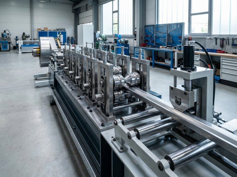
Core Machine Components and Their Forming Roles
The strip feed system controls entry tension and alignment; any lateral deviation at this stage propagates through all downstream forming stations as a cumulative dimensional error. Progressive roller die stations apply incremental bend angle to the strip, with each station adding 10–20 degrees of form depending on profile complexity and material yield strength. The straightening section corrects strip camber before final forming; skipping straightener calibration is a common cause of clamp bow that only appears after cutting, not during in-process inspection. Integrated punching and cutting units complete the clamp profile in-line, eliminating secondary operations and the re-fixturing tolerance loss that accompanies them.
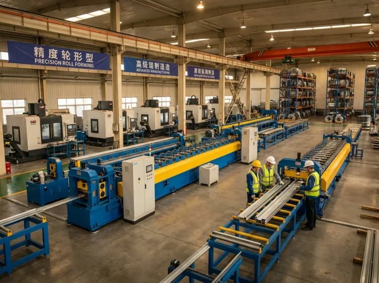
Application Industries and Output Requirements by Sector
Automotive exhaust applications—including turbo coupling and manifold connections—require concentricity tolerance within ±0.3 mm and material compatibility with SUS304 stainless at gauges from 0.8 to 1.2 mm. Ventilation and HVAC clamp production operates at larger diameter ranges and typically uses galvanized steel strip, which introduces zinc adhesion risk on roller die surfaces if die surface treatment is not specified. Industrial piping and connector applications emphasize pressure rating consistency over diameter variety, making die wear tracking the primary ongoing quality variable rather than changeover time.
Rolling Speed Is Not Your Primary Optimization Target
Rolling speed selection for V band clamp forming varies by material gauge, strip width, and roller die station count—with thin gauge strip at 0.5 mm requiring reduced line speed for dimensional stability while mid-gauge material at 0.8 to 1.2 mm represents the optimal consistency window across most V-clamp profiles. Suppliers who lead with maximum speed ratings of 25 m/min are measuring machine capability under ideal conditions with mid-gauge mild steel, not your specific production scenario. We typically find that optimizing for 12–18 m/min across most gauge and strip width combinations produces lower scrap rates than chasing maximum throughput figures from a specification sheet—though this range assumes standard mild steel or stainless forming conditions, and actual optimal speed varies by die profile complexity and material work hardening rate; verify the correct range for your production material through a supervised factory test before finalizing the speed specification.
When the assumption is made that maximum rolling speed produces maximum output without verifying material gauge compatibility, the result is often dimensional drift and scrap rates above 5–8%, which requires slowing the line, recalibrating die stations, and scrapping the out-of-tolerance run—negating every cycle time advantage the speed setting provided.
How Speed Interacts With Material Gauge and Strip Width
Thin gauge strip at 0.5–0.8 mm has insufficient rigidity to maintain lateral alignment at high forming speeds, causing strip wander that produces non-concentric clamps. Mid-gauge strip at 0.8–1.2 mm represents the practical operating window where forming forces, strip stiffness, and die engagement are balanced. In our experience, mid-gauge strip at 0.8–1.2 mm delivers consistent dimensional output in the 12–18 m/min range across typical 1–2 week production runs; verify this range on your production material through supervised factory testing before committing to a speed specification. Heavy gauge strip at 1.2–1.5 mm shifts the limiting variable from speed to motor torque; running at 25 m/min with insufficient motor power produces forming incompletion at station transitions, not speed-related dimensional error.
Cycle Time Calculation That Accounts for Scrap Rate
A machine running at 25 m/min with a typical 7–11% scrap rate may produce fewer acceptable clamps per shift than the same machine optimized to 15 m/min at 3–5% scrap—illustrating that speed alone does not maximize output. We calculate effective cycle time by multiplying nominal line speed by (1 − scrap fraction) and then comparing that output against the 12–18 m/min optimized baseline before finalizing speed specification. Verify your target cycle time against machine speed range using production data from a supervised factory test run, not marketing claims.
Critical Specifications Checklist for V Band Clamp Roll Forming Machines
V band clamp roll forming machine specification verification varies by production material, target clamp diameter, integration requirements, and facility electrical standard—with roller die hardness and voltage specification representing the two variables most commonly misaligned at the point of purchase. We structure this section around the ten factors that directly determine whether a machine performs to production requirements on day one or requires costly post-delivery modification.
| Selection Factor | Specification Range | Decision Threshold |
|---|---|---|
| Material thickness range | 0.5–1.5 mm | Match to product gauge ±0.1 mm |
| Strip width capacity | 80–300 mm | Verify against clamp diameter range |
| Rolling speed | 0–25 m/min | Optimize for 12–18 m/min (consistency) |
| Roller die material | Cr12, HRC 58–62 | Require hardness certificate |
| Motor power | 5.5–22 kW | Match to material and forming load |
| Voltage specification | 380V 3-phase 50Hz | Verify US conversion requirement |
| Tolerance control | ±0.5 mm dimensional | Typical for standard applications; verify against your specific flange dimensional requirements and assembly fit tolerance |
| Tooling changeover time | Design-dependent | Request live changeover demonstration |
| Automation level | Manual to servo | Assess against labor cost and volume |
| Punching/cutting integration | In-line or secondary | Confirm modular add-on compatibility |
Roller Die Hardness—The Specification Most Buyers Underweight
Roller die performance for V band clamp profiles depends on die material hardness relative to strip material yield strength—with Cr12 dies at HRC 58–62 representing the verified operating range for standard forming applications, with the acceptable range shifting toward the upper end when strip material yield strength is higher, as with SUS304 at thin gauge. Dies below HRC 58 show measurable dimensional drift when running SUS304 stainless strip within 8–12 weeks of production start. SUS304 at 0.5 mm gauge causes visible surface hardness degradation on dies below HRC 58 within 80–120 runtime hours at standard forming speeds of 12–18 m/min, with wear accelerating at higher speeds or lower die hardness; Q235 mild steel extends die life beyond 300 hours, depending on line speed, die surface treatment specification, and strip gauge, under standard forming conditions. We require hardness certification and material coupon testing on your specific strip grade before executing any purchase agreement.
Material Compatibility—Q235, SUS304, and Galvanized Steel Trade-offs
Q235 mild steel produces lower tooling wear rates and suits standard carbon steel clamp production where corrosion resistance is handled by post-forming coating or application environment does not demand it. SUS304 stainless delivers the corrosion-resistant clamp output required for exhaust and wet-environment piping, but the higher material yield strength accelerates die wear and demands a verified hardness specification and replacement interval plan from the supplier. Galvanized steel protects the clamp surface through the zinc coating applied before forming, but requires roller die surface treatment to prevent zinc adhesion buildup that progressively alters die geometry and shifts clamp dimensional tolerance. Specifying your target material after die configuration is finalized creates expensive retrofit situations that we consistently see in buyer projects that skipped the material-first specification sequence.
Voltage, Gear Oil, and Electrical Variables US Buyers Miss
Voltage specification for Asian-sourced V band clamp roll forming machines is typically 380V 3-phase 50Hz, while US industrial facilities operate at 460V 3-phase 60Hz—and overlooking this difference during the inquiry stage creates procurement delays typically ranging from 4–6 weeks, depending on transformer availability and local electrical contractor scheduling, when a step-down transformer or motor rewinding is required after delivery. We specify voltage compatibility as a line-item requirement during initial inquiry, not as an afterthought during installation planning. Standard practice for industrial gearbox drives is SAE 90 (approximately 18 cSt) hyperbolic gear oil; however, confirm the exact oil grade and supplier-documented change intervals with your machine supplier’s documentation before accepting delivery, as substituting general-purpose gear oil accelerates gearbox wear and voids most supplier service agreements.
Flange Compatibility and Clamp Diameter Range
Clamp diameter output range for V band roll forming machines varies by strip width capacity and forming station configuration—and must be verified against your existing flange specifications before any other selection variable is evaluated. Machines with fixed strip width capacity cannot accommodate diameter variation across a product family without tooling change; if your product line spans multiple diameters, verify that tooling changeover time and cost are acceptable before committing to a machine configuration. Confirm flange type—single bead or double bead—against the machine’s forming station profile, as a mismatch requires station redesign that suppliers do not always disclose upfront.
Common Mistakes That Drive Post-Delivery Retrofits
Three misalignment patterns appear consistently in post-delivery retrofit discussions we have across V band clamp roll forming projects—patterns we encounter in the majority of buyer projects where these oversights occurred. First, buyers evaluate die hardness after selecting machine price tier rather than before—resulting in under-specified Cr12 dies below HRC 58 that fail prematurely when SUS304 strip enters the line. Second, voltage specification is treated as an installation detail rather than a procurement-stage requirement, which converts a one-line inquiry item into a 4–6 week delay and unplanned transformer cost. Third, strip material is confirmed only after the die configuration is finalized, forcing tooling redesign that the supplier did not price into the original agreement. Addressing all three at the inquiry stage—before supplier selection—eliminates the conditions that produce these retrofit situations.
V-Band Clamp Roll Forming Machines Compared by Automation Level and Integration Scope
Automation level selection for V band clamp roll forming lines depends on production volume per shift, operator skill availability, diameter changeover frequency, and in-line integration requirements—with manual configurations suitable for low-volume variety production and servo-controlled systems delivering measurable consistency advantages at volumes above approximately 500 clamps per shift as a practical heuristic, though the actual threshold depends on clamp diameter, material gauge, and acceptable operator skill cost in your facility. We align automation level selection with labor cost context and downstream integration scope rather than defaulting to the highest automation tier available.
The table below maps automation level to production volume, labor skill requirements, changeover speed, and integration capability:
| Configuration | Volume Suitability | Labor Requirement | Changeover Speed | Integration Capability |
|---|---|---|---|---|
| Manual | Low volume, high variety | 1–2 operators, higher skill | Slow, manually adjusted | Limited |
| Semi-automatic | Mid volume, moderate variety | 1–2 operators, moderate skill | Moderate | Partial punch/cut |
| Servo fully automatic | High volume, consistent profile | Monitoring and loading only | Fast, programmable | Full punch, cut, packaging |
Manual and Semi-Automatic Configurations
Across our recent projects with facilities transitioning to in-house V band clamp production, operator technique variance has emerged as the primary dimensional consistency driver in manual configurations—a pattern we address through operator training protocols before production ramp. Labor requirement is 1–2 operators per shift with higher skill dependency for maintaining dimensional consistency across a full production run. Tooling changeover between clamp diameters requires manual adjustment of each forming station, producing longer setup intervals that reduce effective daily output when product variety is high.
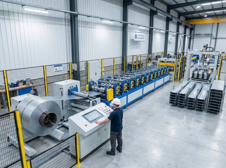
Servo-Controlled Fully Automatic Systems
Servo control enables speed modulation matched precisely to material gauge and profile complexity at each forming station, producing measurable consistency improvement over mechanically fixed-speed drive systems. Labor requirement reduces to line monitoring and strip loading, with output variation driven by material quality rather than operator technique. We design fully automatic V band clamp lines as configurable systems—punching, cutting, and automatic packaging added as modular units rather than fixed configurations—so that integration scope can be expanded as production volume grows.
Punching, Cutting, and Packaging Integration Decision
Integrated punching eliminates secondary bolt hole operations and the re-fixturing tolerance error they introduce; verify punch tonnage compatibility with your clamp wall thickness and bolt hole diameter specification before confirming integration. In-line cutting method—shear or rotary—affects clamp end geometry and must be confirmed against assembly fit tolerance, as rotary cutting produces a cleaner end profile that matters in tight-clearance flange assemblies. Automatic packaging integration reduces post-forming labor but requires floor space allocation and conveyor layout planning during the initial line layout consultation, not after equipment arrival.
How to Verify a V Band Clamp Machine Supplier Before Purchase
Supplier verification for V band clamp roll forming machines depends on documentation completeness, factory testing transparency, and post-sale support capability—with ISO 9001 certification as the minimum quality management baseline and factory test video documentation as the first verification deliverable we request before advancing any purchase discussion. Suppliers who cannot produce a dimensional test report within ±0.5 mm tolerance on clamps produced at rated capacity are not ready for procurement discussion.
Documentation and Certification Baseline
ISO 9001 certification establishes that the supplier operates a documented quality management system with traceable production records—it does not verify machine performance on your specific material, which is why documentation review is a starting point, not a conclusion. Request the following before advancing to commercial negotiation: CE or equivalent safety certification for the machine’s control systems, hardness test certificates for roller die material at the stated HRC value, dimensional inspection report from a factory test run on the clamp profile matching your target, and electrical compliance documentation covering your facility’s voltage standard. Suppliers who cannot produce all four within five business days of request are indicating documentation gaps that will compound during installation and warranty claim processes.
Factory Testing Protocol—What to Request and Why
Factory acceptance testing for V band clamp roll forming machines should include a witnessed or video-documented production run of minimum 50 clamps on the buyer’s target material grade and gauge—not on supplier-supplied mild steel substitutes. In projects where buyers accept supplier-produced test clamps on standard mild steel without running their actual production material, we typically find that die wear rates and dimensional stability require additional verification when SUS304 or galvanized strip enters the line after delivery. Request a dimensional inspection report covering clamp outer diameter, V-profile depth, and concentricity measured across a sample of 10 clamps from the test run, with inspection data referenced against the agreed tolerance specification. Video documentation of the test run should show strip feed entry, forming station sequence, and cutting output in a single continuous recording—edited clips do not provide the process continuity evidence needed to assess forming consistency.
Post-Sale Support Scope—Training, Spare Parts, and Remote Assistance
Post-sale support capability for V band clamp roll forming lines varies by supplier size and export experience—and self-guided installation using translated documentation typically extends commissioning by 2–4 weeks compared to supplier-supported installation, depending on operator familiarity with the machine type and documentation language quality. Verify the following before contract execution: on-site commissioning support availability and cost, spare parts inventory for roller dies, drive components, and cutting blades with confirmed lead times, remote technical assistance scope including video call availability in your time zone, and warranty terms covering both mechanical failure and dimensional performance. Suppliers who offer only email support with response windows exceeding 48 hours represent a commissioning risk for buyers without in-house roll forming engineering capability.
Common Mistakes That Drive Post-Delivery Retrofits
See the Specifications Checklist section above for the three misalignment patterns—die hardness underspecification, voltage oversight, and material-second configuration sequencing—that consistently produce retrofit costs. In the verification context, the fourth pattern is accepting factory test results on substitute material rather than requiring production-grade strip in the acceptance test. This oversight is correctable at the inquiry stage by specifying material grade and gauge as a line item in the factory acceptance test protocol before issuing a purchase order.
Conclusion
Choosing a V band clamp roll forming machine correctly requires aligning roller die hardness, material gauge compatibility, automation level, and voltage specification before evaluating speed or price—and verifying each variable through documented factory testing rather than accepting specification sheet claims. At Co-effort, our engineering team has seen the failure mode directly: when the assumption is made that standard Cr12 dies at HRC 60 will perform adequately on SUS304 stainless without running a material coupon test, the result is die degradation within the first production quarter, requiring replacement tooling and a dimensional recalibration cycle that the original machine price did not anticipate. Our in-house hardness testers, profilers, and forming-machine test rigs exist specifically to verify performance on buyer-supplied material before delivery, not after installation reveals a specification gap.
The specification sequence that produces reliable outcomes is consistent: confirm production material grade and gauge first, match roller die hardness to that material, verify voltage compatibility against your facility standard, select automation level against your actual volume and labor cost structure, and then evaluate price within the configuration that meets those requirements. Reversing this sequence—starting with price or speed and working backward to material compatibility—is the pattern that produces retrofit costs exceeding the original price difference that drove the selection.
To move forward, share your target clamp profile drawing, strip material specification, and production volume requirement with our engineering team. We will return a verified machine configuration with factory test protocol before any commercial discussion advances.
FAQ
What is the minimum production volume that justifies a V band clamp roll forming machine over outsourced supply?
Minimum volume justification for in-house V band clamp roll forming depends on clamp unit cost from current suppliers, tooling amortization period, and in-house labor cost structure—with no universal breakeven volume applicable across all facility types. At low volumes with high diameter variety, outsourcing typically remains more cost-effective until monthly clamp consumption exceeds the tooling cost recovery threshold at your production labor rate. Calculate breakeven using your current per-unit supply cost, estimated machine amortization over 5 years, and loaded labor cost per shift, then compare against projected in-house unit cost at realistic scrap rates—not maximum rated speed, which applies only under ideal test conditions.
Which strip material is most compatible with a standard V band clamp roll forming machine?
Strip material compatibility for standard V band clamp roll forming machines is highest with Q235 mild steel at 0.8–1.2 mm gauge, which produces the lowest die wear rates and the widest forming speed window. SUS304 stainless steel is compatible but requires verified die hardness at HRC 58–62 minimum—shifted toward the upper end of that range for thin gauge SUS304—and planned die replacement intervals based on runtime hours rather than calendar time. Galvanized steel is compatible with surface-treated roller dies; untreated dies accumulate zinc adhesion that progressively shifts clamp dimensional tolerance outside acceptable range.
Can a V band clamp roll forming machine be customized for non-standard clamp profiles?
Non-standard V band clamp profiles—including asymmetric V-angles, double-bead flange engagement, or diameter ranges outside standard tooling—require custom roller die design and additional forming station configuration. In our custom profile projects, the determining variable is whether the non-standard geometry can be achieved through progressive forming increments within the station count of the base machine, or whether additional stations must be added to the line. We evaluate custom profile feasibility using the target cross-section drawing and material specification before quoting tooling, because profile complexity directly determines station count and die cost—both of which affect the overall machine configuration and delivery timeline.
How do I verify that a supplier’s machine will meet my dimensional tolerance requirements before purchase?
Dimensional tolerance verification before purchase depends on requiring a factory acceptance test run on your specific production material—not supplier-supplied substitute stock—with inspection data documented against your agreed tolerance specification. In our verification process, we require a minimum 50-clamp test run on buyer-supplied strip grade and gauge, with dimensional inspection covering outer diameter, V-profile depth, and concentricity measured across a 10-clamp sample from that run. Suppliers who cannot meet this requirement before purchase will not reliably meet it after delivery; the verification protocol is the same whether the purchase is domestic or cross-border. We provide full test documentation including video of the continuous production run and a dimensional report referenced to the agreed tolerance before any shipment is authorized.
What ongoing maintenance schedule should I plan for a V band clamp roll forming machine?
Ongoing maintenance scheduling for V band clamp roll forming machines depends on production material, line speed, and shift hours per week—with die inspection intervals determined by runtime hours on the specific material rather than calendar time. Inspect roller die surfaces for hardness degradation and dimensional drift every 80–100 runtime hours when running SUS304 stainless; mild steel production allows extended intervals to 250–300 hours before inspection, depending on line speed and die surface treatment. Gearbox oil changes should follow supplier-documented intervals using the specified oil grade—confirm this interval and oil specification in writing before accepting delivery, as post-delivery documentation gaps are a recurring issue in cross-border machine procurement.